|
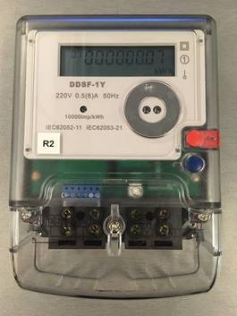
Meter: The electricity meter has an RS485 serial communication port so that it can output many parameters including Voltage, Current, Frequency, Power, Power Factor, Energy (kWh), Relay Status, Temperature, and some Warnings and Flags. This meter can also be controlled by the input signal to serve as a switch, which makes it possible for our remote control. The communication protocol is based on A Modbus RTU protocol. The basic schema can be found in the appendix and on the github repository.
|
|
|
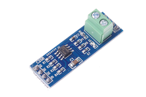
Signal converter: We choose to use a RS485 to TTL Converter to convert RS485 communication from the smart meters to TTL serial communication that the ARM chips can easily process. The converter chip is manufactured by Maxim Integrated.
|
|
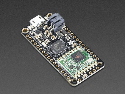
Remote Node: For the Remote Node we used an Adafruit Feather M0 embedded device. Its main chip is an ATSAMD21G18 ARM Cortex M0 processor, clocked at 48 MHz and at 3.3V logic. This is a very powerful board with small size and is very cheap. Thus it is more competitive than other expensive controllers if it can satisfy the needs of users. It has 256KB of flash and 32KB of RAM. In our project, we used a RFM9x LoRa 433 MHz radio module. The LoRa module is used to transport data from remote nodes to controllers. Considering that our project is specified to be implemented in rural areas a radio communication module is better than common GSM or GPRS networks.
|
|
|
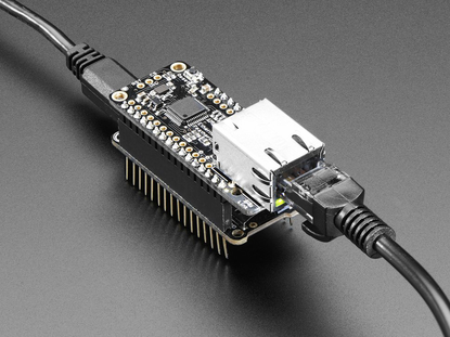
Main Controller: The Main Controller is also an Adafruit Feather M0 with a 433MHz LoRa radio module to receive data from remote meters and broadcast a switch relay command. Since we need to build up a web server, an Ethernet shield was also needed. We choose an Adafruit Ethernet shield with Wiznet W5500 Ethernet chip to enable the Arduino board to connect to the Internet. Using all of the components we are able to connect the controller to the internet, send HTTP requests, and RF communication messages.
|
